Since the use of first simple bridges made from a single beam that had to
endure all the forces of tension, compression, torsion and shear forces by
itself, engineers and architects tried to develop new and better techniques
for spanning the gaps between one point of terrain to another. Eventually,
the entire engineering field was formed, and dozens upon dozens of bridge
designs were created utilizing many components, parts and brand new
terminology that describe them.
All the basic components are placed inside three main bridge areas –
Foundation (which holds the shallow or deep base of the
bridge and transfers it’s load to the bearing strata, this includes
foundations below the main span of the bridge and the abutments below
starting points of the bridge),
Substructure (piers,
abutments, spandrels, caps, bearings, and other components that holds the
upper construction) and
Superstructure (all the parts of
the bridge that are mounted on top of the supporting substructure system,
it covers elements such as decking, girders, slab, and everything placed
above the main deck such as posts, steel truss system, bridge girder,
cable-stayed system, cable suspended systems and more).
Basic Components and Parts of Bridge Structures
The bridge structure consists of the following components:
- Superstructure or decking component
- Bearings
- Substructure Components
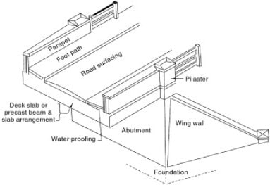
Fig: Semi-Through Section of a Concrete Slab Road Bridge
Superstructure Components of Bridges
The
superstructure of the bridge structure consists of deck slab, girder,
truss etc. These components vary based on the type of bridge (whether
concrete or steel or composite). Superstructure of the bridge bears the
load passing over it. This helps in transmitting the forces formed by
the loads to the below substructures.
Decks
The
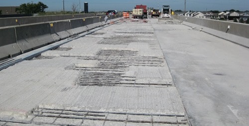
decking is considered as the road or the rail surface of the bridge. The
decks are supported by the girders or the huge beams that is in turn
supported by the piers. The whole arrangement is supported with a deep
foundation mainly piles and cap arrangement.
Bearings in Bridges
The
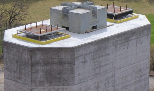
loads received by the decks are properly and safely transmitted to the
substructure with the help of bearings. These are components of bridge
that enables even distribution of load on the substructure material.
This transmission is very essential in situations where the substructure
is not designed to take the load action directly.
The
bearings in bridges allows the longitudinal movement of the girders.
This movement is created due to the forces acting on the longitudinal
direction. The forces due to the moving loads and the variation in
temperature are the main causes for longitudinal forces.
The
selection of bearing is dependent on certain parameters, which are:
Loads acting, the geometry, the extent of maintenance, the clearance
available, the displacement, rotation and deflection policy,
availability, preference of the designer, the construction tolerances,
and the cost criteria.
For the bridge design, all the
above-mentioned aspect is considered for the design and the choice of
bearings. The designer must consider the bearing arrangement in the
bridge construction as a separate system.
In most of construction
practice, the bearing is selected or the decision for bearing is done in
the last moment. This results in increase of maintenance in the future,
which must be avoided.
Substructure Components of Bridges
The components involved in substructure of bridges are:
- Piers
- Abutments
- Wing Walls and the Returns
- Foundation
Piers
The
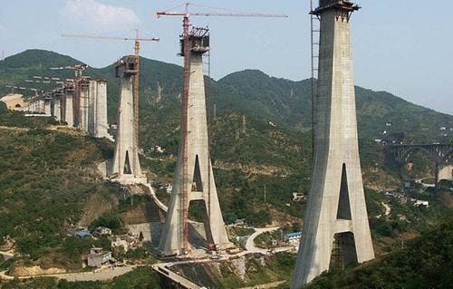
piers are vertical structures used to support deck or the bearings
provided for load transmission to underground soil through foundation.
These structures serve as supports for the bridge spans at intermediate
points.
The pier structure has mainly two functions:
- Load transmission to the Foundation
- Resistance to the horizontal forces
Most
of the cases, piers are designed to resist the vertical loads alone. In
areas which lie in the seismic zone, it is recommended to design the
pier for lateral loads also.
Most
of the piers are constructed using concrete. Steel for the construction
of pier is used in very few cases till now. Use of composite columns
i.e. steel columns filled with concrete is used as new technology of
pier construction.
The pier is a vertical member that resist the
forces by means of shear mechanism. These forces are mainly lateral
forces. The pier that consist of multiple columns are called as bent.
Types of Piers in Bridge Construction
There are different types of piers based on the structural connectivity, the shape of the section and the framing configuration.
- Based on the structural connectivity, the pier can be classified as monolithic or cantilevered.
- Based on the shape of the section pier can be classified as solid or hollow, hexagonal, round or octagonal or rectangular.
- Based on the framing configuration the pier can be classified as single or multiple column bent, hammerhead or pier wall type.
Abutments
Abutments
are vertical structures used to retain the earth behind the structure.
The dead and the live loads from the bridge superstructure is supported
by the bridge abutments.
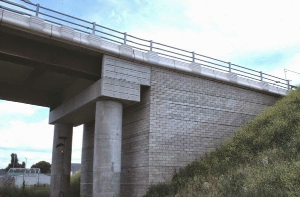
The
abutments are also subjected to lateral pressures mainly from the
approach embankment. The design loads on the abutment is mainly
dependent on the:
- Type of abutment selected
- The sequence of construction
The figure below shows the primary functions carried out by an abutment.
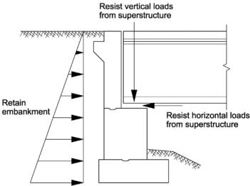
Fig: Abutments in Bridge Construction- Primary Functions
As
seen from the above figure, the abutments have the design requirements
similar to retaining walls as well as in pier construction. The
abutments are primarily designed to resists the overturning and sliding.
More focus is on the stability of the whole system.
The special
care has to be provided for the foundations of abutments. The abutment
foundation must overcome the problems of differential settlement and
excessive movements caused due to lateral forces or loads.
The below figure shows the components of abutments.
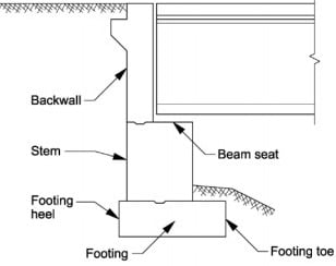
Fig: Abutments Components
Wing Walls and Returns
Structures
constructed as an extension of the abutments to retain the earth
present in the approach bank are called wing walls. This portion will
otherwise have a natural angle of repose. These are retaining walls
constructed adjacent to the abutments. This wall can be constructed
either integrally or independent with the abutment wall.
The rear of the wall must consider three design loads while designing. This includes:
- The earth pressure from the backfill
- The surcharge from the live loads or the compacting plant
- The hydraulic loads from the saturated soil conditions
The
stability of the wing wall is mainly based on its resistance against
the active earth pressures. The structural elements of the bridges are
hereby designed and constructed to resist the earth pressures at rest.

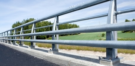
Parapets and Handrails/ Guard Rails or Curbs
These
components of bridges are not of structural importance, but provided
for the safety concerns. These are provided above the decks. This will
help in prevention of the vehicle from falling off the bridge into the
water body below or as a means for the separation of traffic streams.
Foundation of Bridges
Foundation
are structures constructed to transmit the load from the piers,
abutments, wing walls and the returns evenly on the strata.
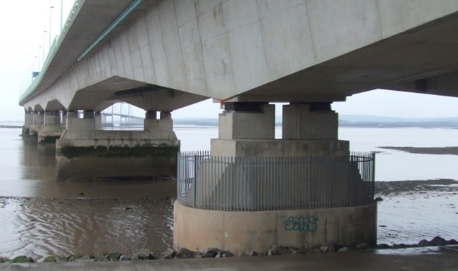
The
foundation provided for bridge structures are deep in sufficient manner
to avoid scouring due to the water movement or to reduce the chances of
undermining.
Pier: A pier is a raised structure that sits in a
body of water to support a bridge. The open structure of a pier allows
water to pass through it, preventing pressure from building up against
it.
Pile: A pile is a vertical support
structure that’s used, in part, to hold up a bridge. It can be made
of wood, concrete, or steel. A pile is hammered into the soil beneath
the bridge until the end of it reaches the hard sub layer of compacted
soil or rock below. Piles hammered to this depth leverage the grip and
friction of the soil surrounding it to support part of the load of the
bridge deck.
Side plate: A side plate is a linear bearing that is
used as a part of an expansion joint of a bridge. One plate is
typically fixed, and the other slides over it to accommodate expansion
and contraction. This provides the bridge structure with support while
accommodating shifts in temperature.
Skew arch: A skew (sometimes referred to as an
oblique arch) is a style of arch where its faces are not perpendicular
to the abutments of the bridge. The interior of the arch takes the form
of a parallelogram, rather than a rectangle or square. Using a skew arch
allows a bridge to cross a span at virtually any angle, rather than
just a straight line.
Superstructure: The superstructure is the part of
the bridge that absorbs the live load. (The abutment, piers, and other
support elements are referred to as the substructure.)
https://theconstructor.org/


 கோவிலில்
நுழைந்து செல்லும்போது மகாமண்டபம், அர்த்தமண்டபம், கருவறை ஒன்றுக்கொன்று
சற்று பள்ளமாக அமைந்திருப்பதால் `குடிபள்ளம்’ எனவும் இப்பகுதியில்
அழைக்கின்றனர். கோவிலில் அம்மன் `ஆனந்தவல்லி’ என்ற பெயருடன்
தனிச்சன்னிதியில் அங்குசம் – பாசம், அபய – வரத கரங்களுடன் கருணை பொங்கும்
முகப்பொலிவுடன் அருள்மழை பொழிகிறாள். திருச்சுற்றில் பரிவார கோவில்கள்
உள்ளன. இவற்றில் வடகிழக்கில் காணப்படும் சூரியன் திருமேனி தொன்மையானதாகும்.
நுழைவு வாயிலில், மேல் கோபுரம் இல்லாமல் தட்டையாக உள்ளது.


