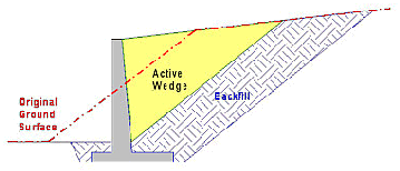
Retaining walls provide lateral support to vertical slopes of soil. Theyretain soil which would otherwise collapse into a more natural shape. The retained soil is sometimes referred to asbackfill.
Retaining walls can be constructed of many different materials and with a variety of building techniques. This discussion will focus on rigid, monolithic, poured concrete walls as the structural material, but steel, timber, and reinforced soil are often used too.
This retaining wall discussion will focus on walls that are constructed from the bottom up and where a stable backslope exists (at least temporarily) prior to wall construction. With poured concrete retaining walls, backfill is placed between the wall and the slope after the wall is constructed.
This discussion will talk about the walls themselves, their design and some important construction considerations. It will not talk about groundwork or compaction, since these are entire topics on their own right. Designers and builders of any kind of retaining wall should be familiar with and follow the procedures and methods for soil preparation and backfill compaction methods dictated by the appropriate local building codes.
General Retaining Wall Design
Retaining wall design and wall type selection is driven by several factors.
These factors include:
- Cost
- Required wall height
- Ease and speed of construction
- Ground water conditions and soil characteristics.
Other factors can include skilled labor and material availability, building codes, site accessibility, aesthetics, local building practice, etc. Ultimately, all retaining walls serve to hold back a vertical or near vertical face of soil that would, without adequate retention, cave, slump or slide to a more natural slope.
In most states, retaining wall designs taller than about four feet must be designed by or approved by a qualified, licensed professional engineer. Additionally, it is important to check with and adhere to local building codes prior to any construction, even when walls are shorter than four feet. Retaining walls are, and should always be viewed as load bearing members first, and aesthetic groundscapes second.
Designing any retaining wall requires a knowledge of lateral earth pressure.
Once the lateral earth pressures are known, the wall is checked for stability. This includes checks for wall overturning, base sliding, and soil bearing capacity failures. After the wall is sized, each wall member is checked for adequate strength and steel reinforcing is determined.
One of the most common and telling failures of retaining walls is the inevitable tilting, cracking and bowing of brick, timber and concrete block retaining walls built by homeowners, well meaning builders, and landscapers. These "problems" truly are failures, since the wall has not performed the task it was built to do, and that is to hold back the soil.
The failures also clearly demonstrate the lack of knowledge or design that is required by a successful retaining wall design. By understanding how a wall works, and how it can fail, it is possible to engineer a retaining structure that will meet all foreseen environmental, structural and construction demands.
Building Codes for Retaining Walls
most states, retaining wall designs taller than about four feet must be designed by or approved by a qualified, licensed professional engineer. Additionally, it is important to check with and adhere to local building codes prior to any construction, even when walls are shorter than four feet. Retaining walls are, and should always be viewed as load bearing members first, and aesthetic groundscapes second
What is Lateral Earth Pressure?
Designing any retaining wall requires knowledge of lateral earth pressure, the pressure developed by the backfill.
It is the force generated by the lateral earth pressure that constitutes a large part of the load that the wall must carry.
To determine the lateral earth pressure acting against the retaining wall, several soil parameters must be known in order for the qualified engineer to assess a particular wall design and its overall stability. These basic soil parameters include:
- Soil unit weight
- Angle of internal friction (for sands)
- Cohesion and plasticity indices (for clays)
- The water table location.
Once the lateral earth pressures are known, the wall is checked for stability. This includes checks for wall overturning, base sliding, and soil bearing capacity failures. After the wall is sized, each wall member is checked for adequate strength and steel reinforcing is determined.
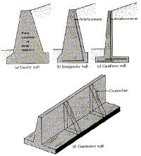
Gravity Poured Concrete
Retaining Walls
- Gravity retaining walls depend on their own weight and any soil resting on the concrete in resisting lateral earth forces.
- They are generally economical up to 10 feet in height for cast concrete structures.
- Usually are sufficiently massive to be unreinforced.
- Monolithic cast walls are generally formed on site
Cantilever Retaining Walls
Cantilever retaining walls are constructed of reinforced concrete. They consist of a relatively thin stem and abase slab. The base is also divided into two parts, theheel and toe. The heel is the part of the base under the backfill. The toe is the other part of the base.
- Use much less concrete than monolithic gravity walls, but require more design and careful construction.
- Generally economical up to about 25 ft. in height.
- Can be precast in a factory or formed on site.
Counterfort retaining walls are similar to cantilever walls except they have thin vertical concrete webs at regular intervals along the backside of the wall. These webs are known as counterforts.
Counterfort retaining walls:
- The counterforts tie the slab and base together, and the purpose of them is to reduce the shear forces and bending moments imposed on the wall by the soil. A secondary effect is to increase the weight of the wall from the added concrete.
- Can be precast or formed on site.
- Counterfort retaining walls are more economical than cantilever walls for heights above 25 ft.
Monolithic Concrete Retaining
Wall Proportions
Proper proportioning of a retaining wall is just as important to its construction as its structural design. Construction-friendly proportions facilitate proper concrete placement and provide sufficient room for structural reinforcement.
In addition to basic structural requirements, wall dimensions (generally member thickness) are also affected by the required minimum reinforcement cover. This can add several inches to the wall's thickness dimensions, and can vary depending on the severity of exposure, soil type and reactivity, etc.
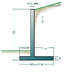
In general, the top of the stem of any cast concrete retaining wall should not be less than 12 inches for the proper placement of concrete.
The depth to the bottom of the base slab should be kept at a minimum of two feet. However, it should always be below the seasonal frost line, and that often is much deeper in northern climates.
The length of the base slab is usually about 50% to 70% of the total height of the wall (bottom of base to top of stem).
For cantilever and counterfort walls, the stem thickness at the base is often about 10% of the total wall height, as is the base slab thickness.
Counterfort retaining walls have counterforts spaced at center-to-center distances of about 30% to 70% of the total wall height.
In some cases, a footing key is included to increase resistance to sliding. The footing key is generally an extension of the stem and extends below the bottom of the base.
Provisions for Joints in the Construction of Walls
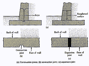
Cast concrete retaining walls may be constructed with any or all of the following joints:
Construction Joints: These are vertical or horizontal joints that are used between two successive pours of concrete. Keys are used to increase the shear resistance at the joint. If keys are not used, the surface of the first pour is cleaned and roughened before the next placement of concrete. Keys are almost always formed in the base to give the stem added sliding resistance. The base is formed first, and the stem constructed afterwards.
Contraction Joints: These are vertical joints or grooves formed or cut into the wall that allows the concrete to shrink without noticeable harm. Contraction joints are usually about 0.25 inches wide and about 1/2 to 3/4 inch deep, and are provided at intervals of not exceeding 30 feet.
Expansion Joints: Vertical expansion joints are incorporated into the wall to account for expansion due to temperature changes. These joints may be filled with flexible joint fillers. Greased steel dowels are often cast horizontally into the wall to tie adjacent sections together. Expansion joints should be located at intervals up to 90 feet.
Backfill Drainage of Retaining Walls
One area that can be commonly overlooked, or at least underestimated, is the necessity to drain the backfill of rainwater and/or groundwater. Hydrostatic pressure can cause or induce retaining wall failure, or at least damage.
Drainage of water as a result of rainfall or other wet conditions is very important to the stability of a retaining wall. Without proper drainage, the backfill can become saturated, which has the dual impact of increasing the pressure on the wall and lessening the resistance of the backfill material to sliding. Granular backfill material offers the benefits of good drainage, easy compaction, and increased sliding resistance.
Drainage systems usually utilize weepholes and drainage lines.
Weepholes actually penetrate the retaining wall and drain the area immediately behind the wall. Weepholes should have a minimum diameter so as to permit free drainage. For large walls, 4 inch weepholes are common. Adequate spacing between weepholes allows uniform drainage from behind the wall. Weepholes should always have some kind of filter material between the wall and the backfill to prevent fines migration, weephole clogging, and loss of backfill and caving.
Drainage lines are often perforated and wrapped in geotextile or buried in a granular filter bed, and serve to carry water to the weepholes from areas deeper within the backfill.


No comments:
Post a Comment