How Electricity Works
Humans have an intimate relationship with electricity, to the point that it's virtually impossible to separate your life from it. Sure, you can flee from the world of crisscrossing power lines and live your life completely off the grid, but even at the loneliest corners of the world, electricity exists. If it's not lighting up the storm clouds overhead or crackling in a static spark at your fingertips, then it's moving through the human nervous system, animating the brain's will in every flourish, breath and unthinking heartbeat.
When the same mysterious force energizes a loved one's touch, a stroke of lightning and a George Foreman Grill, a curious duality ensues: We take electricity for granted one second and gawk at its power the next. More than two and a half centuries have passed since Benjamin Franklin and others proved lightning was a form of electricity, but it's still hard not to flinch when a particularly violent flash lights up the horizon. On the other hand, no one ever waxes poetic over a cell phone charger.
In this article, we'll try to provide a less slippery answer. We'll illuminate just what electricity is, where it comes from and how humans bend it to their will.Electricity powers our world and our bodies. Harnessing its energy is both the domain of imagined sorcery and humdrum, everyday life -- from Emperor Palpatine toasting Luke Skywalker, to the simple act of ejecting the "Star Wars" disc from your PC. Despite our familiarity with its effects, many people fail to understand exactly what electricity is -- a ubiquitous form of energy resulting from the motion of charged particles, like electrons. When put to the question, even acclaimed inventor Thomas Edison merely defined it as "a mode of motion" and "a system of vibrations."
For our first stop, we'll travel to Greece, where inquisitive ancients puzzled over the same phenomena that zap you when you touch a metal object after shuffling over the carpet on a cold, dry day.
Electrostatics and Coulomb's Law
Illustration of Leyden jar
Even though they didn't fully understand it, ancient people knew about electricity. Thales of Miletus, a Greek philosopher known as one of the legendary Seven Wise Men, may have been the first human to study electricity, circa 600 B.C. By rubbing amber -- fossilized tree resin -- with fur, he was able to attract dust, feathers and other lightweight objects. These were the first experiments with electrostatics, the study of stationary electric charges or static electricity. In fact, the word electricity comes from the Greek elektron, which means amber.
The experiments wouldn't continue until the 17th century. That's when William Gilbert, an English physician and amateur scientist, began to study magnetism and static electricity. He repeated the research of Thales of Miletus, rubbing objects together and charging them by friction. When one object attracted or repelled the other, he coined the term "electric" to describe the forces at work. He said these forces developed because the rubbing action removed a fluid, or "humour," from one of the objects, leaving an "effluvium," or atmosphere, around it.
This concept -- that electricity existed as a fluid -- persisted into the 1700s. In 1729, English scientist Stephen Gray observed that certain materials, such as silk, didn't conduct electricity. His explanation was that the mysterious fluid described by Gilbert could travel through objects or be hampered from travelling. Scientists even built jars to hold this fluid and study its effects. The Dutch instrument makers Ewald von Kleist and Pieter van Musschenbroek created what is now known as a Leyden jar, a glass jar containing water and a nail that could store an electrical charge. The first time Musschenbroek used the jar, he received a massive shock.
By the later 1700s, the scientific community was beginning to get a clearer picture of how electricity worked.Benjamin Franklin ran his famous kite experiment in 1752, proving that lightning was electrical in nature. He also presented the idea that electricity had positive and negative elements and that the flow was from positive to negative. Approximately 30 years later, a French scientist by the name of Charles Augustin de Coulomb conducted several experiments to determine the variables affecting an electrical force. His work resulted in Coulomb's law, which states that like charges repel and opposite charges attract, with a force proportional to the product of the charges and inversely proportional to the square of the distance between them.
Coulomb's law made it possible to calculate the electrostatic force between any two charged objects, but it didn't reveal the fundamental nature of those charges. What was the source of the positive and negative charges? As we'll see in the next section, scientists were able to answer that question in the 1800s.
Electricity and Atomic Structure
Inside an atom
Toward the end of the 19th century, science was barreling along at an impressive pace. Automobiles and aircraft were on the verge of changing the way the world moved, and electric power was steadily making its way into more and more homes. Yet even scientists of the day still viewed electricity as something vaguely mystical. It wasn't until 1897 that scientists discovered the existence of electrons -- and this is where the modern era of electricity starts.
Matter, as you probably know, is composed of atoms. Break something down to small enough pieces and you wind up with a nucleus orbited by one or more electrons, each with a negative charge. In many materials, the electrons are tightly bound to the atoms. Wood, glass, plastic, ceramic, air, cotton -- these are all examples of materials in which electrons stick with their atoms. Because these atoms are so reluctant to share electrons, these materials can't conduct electricity very well, if at all. These materials are electrical insulators.
Most metals, however, have electrons that can detach from their atoms and zip around. These are called free electrons. The loose electrons make it easy for electricity to flow through these materials, so they're known aselectrical conductors. They conduct electricity. The moving electrons transmit electrical energy from one point to another.
Holy Electricity
In the late 19th century, electricity truly had a noble or even divine reputation -- to the extent that members of the scientific community protested the idea of the electric chair as a degradation of both electricity and the scientific breakthroughs that made electrocuting a criminal possible. What might these critics have thought of such modern marvels as the battery-powered blackhead remover or the dance-floor horror known as the electric slide?
|
Some of us at HowStuffWorks.com like to think of atoms as pet dogs and electrons as a case of fleas. Dogs that lived inside or within a fenced-in area, thereby keeping those pesky fleas contained, would be the equivalent of an electrical insulator. Free-roaming mutts, however, would be electrical conductors. If you had one neighborhood of indoor, pampered pugs and one neighborhood of unfenced basset hounds running wild, which group do you think could spread an outbreak of fleas the fastest?
So, electricity needs a conductor in order to move. There also has to be something to make the electricity flow from one point to another through the conductor. One way to get electricity flowing is to use a generator.
Generators
If you've ever moved paper clips around with a magnet or killed time arranging metal shavings into a beard on a "Wooly Willy" toy, then you've dabbled in the basic principles behind even the most complicated electric generators. The magnetic field responsible for lining up all those little bits of metal into a proper Mohawk haircut is due to the movement of electrons. Move a magnet toward a paper clip and you'll force the electrons in the clip to move. Similarly, if you allow electrons to move through a metal wire, a magnetic field will form around the wire.
Thanks to Wooly Willy, we can see that there's a definite link between the phenomena of electricity and magnetism. A generator is simply a device that moves a magnet near a wire to create a steady flow of electrons. The action that forces this movement varies greatly, ranging from hand cranks and steam engines to nuclear fission, but the principle remains the same.
One simple way to think about a generator is to imagine it acting like a pump pushing water through a pipe. Only instead of pushing water, a generator uses a magnet to push electrons along. This is a slight oversimplification, but it paints a helpful picture of the properties at work in a generator. A water pump moves a certain number of water molecules and applies a certain amount of pressure to them. In the same way, the magnet in a generator pushes a certain number of electrons along and applies a certain amount of "pressure" to the electrons.

Generators form the heart of a modern power station. In the next section, we'll take a look at how one of these stations works.In an electrical circuit, the number of electrons in motion is called the amperage or current, and it's measured inamps. The "pressure" pushing the electrons along is called the voltage and is measured in volts. For instance, a generator spinning at 1,000 rotations per minute might produce 1 amp at 6 volts. The 1 amp is the number of electrons moving (1 amp physically means that 6.24 x 10¹⁸ electrons move through a wire every second), and the voltage is the amount of pressure behind those electrons.
Making Electricity
Stockbyte/Thinkstock
Niagara Falls: It has beauty and a whole lot of kinetic energy that we like to put to use for hydroelectric power.
In Michael Faraday's generator, coils of copper wire rotating between the poles of a magnet produce a steady current of electricity. One way to rotate the disk is to crank it by hand, but this isn't a practical way to make electricity. Another option is to attach the shaft of the generator to a turbine and then let some other energy sources power the turbine. Falling water is one such energy source, and, in fact, the first major plant ever built took advantage of the enormous kinetic energy delivered by Niagara Falls.
George Westinghouse opened that plant in 1895, but the principles of its operation haven't changed much since then. First, engineers build a dam across a river to create a reservoir of stored water. They place a water intake near the bottom of the dam wall, which allows water to flow from the reservoir and through a narrow channel called a penstock. The turbine -- imagine a huge propeller -- sits at the end of the penstock. The shaft from the turbine goes up into the generator. When the water moves across the turbine, it spins, rotating the shaft and, in turn, rotating the copper coils of the generator. As the copper coils spin within the magnets, electricity is produced. Power lines connected to the generator carry electricity from the power plant to homes and businesses. Westinghouse's Niagara Falls plant was able to transport electricity more than 200 miles (322 kilometers).
Not all power plants rely on falling water. Many take advantage of steam, which acts like a fluid and can, therefore, transfer energy to a turbine and, ultimately, to a generator. The most popular way to make steam is to heat water by burning coal. It's also possible to use controlled nuclear reactions to turn water into steam. You can read about the various types of power stations in How Hydropower Plants Work, How Wind Power Works and How Nuclear Power Works. Just keep in mind that they all work on the same basic principle of converting mechanical energy -- spinning turbine -- into electrical energy.
Of course, using a generator to make electricity is just the beginning. After you get your electrons moving along, you'll need an electrical circuit to do anything with it. Find out why next.
Electrical Circuits
When you load a battery into an electronic device, you're not simply unleashing the electricity and sending it to do a task. Negatively charged electrons wish to travel to the positive portion of the battery -- and if they have to rev up your personal electric shaver along the way to get there, they'll do it. On a very simple level, it's much like water flowing down a stream and being forced to turn a water wheel to get from point A to point B.
Whether you are using a battery, a fuel cell or a solar cell to produce electricity, three things are always the same:
- The source of electricity must have two terminals: a positive terminal and a negative terminal.
- The source of electricity (whether it is a generator, battery or something else) will want to push electrons out of its negative terminal at a certain voltage. For example, one AA battery typically wants to push electrons out at 1.5 volts.
- The electrons will need to flow from the negative terminal to the positive terminal through a copper wire or some other conductor. When there is a path that goes from the negative to the positive terminal, you have a circuit, and electrons can flow through the wire.
You can attach any type of load, such as a light bulb or motor, in the middle of the circuit. The source of electricity will power the load, and the load will perform whatever task it's designed to carry out, from spinning a shaft to generating light.
Electrical circuits can get quite complex, but basically, you always have the source of electricity (such as a battery), a load and two wires to carry electricity between the two. Electrons move from the source, through the load and back to the source.
Moving electrons have energy. As the electrons move from one point to another, they can do work. In an incandescent light bulb, for example, the energy of the electrons is used to create heat, and the heat in turn creates light. In an electric motor, the energy in the electrons creates a magnetic field, and this field can interact with other magnets (through magnetic attraction and repulsion) to create motion. Because motors are so important to everyday activities and because they are, in essence, a generator working in reverse, we'll examine them more closely in the next section.
Electric Motors
As we've already discussed, a generator converts mechanical energy into electricity. A motor works on the same principles, but in the opposite direction -- it converts electrical energy into mechanical energy. To do this, a motor needs a special kind of magnet known as an electromagnet. In its simplest form, this consists of an iron bar wrapped in a coil of wire. If you pass an electric current through the wire, a magnetic field is formed in the iron bar, and it becomes a magnet, with definite north and south poles. Turn off the current, and the magnetic properties disappear.
By themselves, electromagnets are useful things. You can use them to pick up metal objects, carry the objects somewhere and then drop them by just turning off the power. For example, roofers use them to pick up nails that have fallen by accident into a homeowner's yard. And wrecking yards have cranes with built-in electromagnets strong enough to pick up and move entire cars.
Electromagnets are especially useful when they're placed on an axis between two stationary magnets. If the electromagnet's south pole is situated against the south pole of one stationary magnet and its north pole against the north pole of the other stationary magnet, the electromagnet will rotate until opposite poles line up. This wouldn't be very helpful, except the polarity of electromagnets depends on the direction of current flow. Pass electric current in one direction, and the magnet's north pole will be on one side; reverse the current flow, and the north pole will be on the opposite side. In motors, a device known as a commutator reverses the direction of flow of electric current. As the poles of the electromagnet flip back and forth, the magnet is able to rotate without interruption. This is a brief explanation of course, so you may want to read How Electric Motors Work for all of the details.
As it turns out, the mechanical energy created in an electric motor can be put to good use in a variety of machines. Many tools in your garage, appliances in your house and toys kids play with rely on motors. Some of these motors require a large current to operate. Others, such as small DC motors used in robots and models, need very little voltage or current to perform efficiently. We'll continue our conversation about voltage and current in the next section.
Voltage, Current and Resistance
As mentioned earlier, the number of electrons in motion in a circuit is called the current, and it's measured in amps. The "pressure" pushing the electrons along is called the voltage and is measured in volts. If you live in the United States, the power outlets in the wall of your house or apartment deliver 120 volts each.
If you know the amps and volts involved, you can determine the amount of electricity consumed, which we typically measure in watt-hours or kilowatt-hours. Imagine that you plug a space heater into a wall outlet. You measure the amount of current flowing from the wall outlet to the heater, and it comes out to 10 amps. That means that it is a 1,200-watt heater. If you multiply the volts by the amps, you get the wattage. In this case, 120 volts multiplied by 10 amps equals 1,200 watts. This holds true for any electrical appliance. If you plug in a light and it draws half an amp, it's a 60-watt light bulb.
Let's say that you turn on the space heater and then look at the power meter outside. The meter's purpose is to measure the amount of electricity flowing into your house so that the power company can bill you for it. Let's assume -- we know it's unlikely -- that nothing else in the house is on, so the meter is measuring only the electricity used by the space heater.
Your space heater is using 1.2 kilowatts (1,200 watts). If you leave the space heater on for one hour, you will use 1.2 kilowatt-hours of power. If your power company charges you 10 cents per kilowatt-hour, then the power company will charge you 12 cents for every hour that you leave your space heater on.
Now let's add one more factor to current and voltage: resistance, which is measured in ohms. We can extend the water analogy to understand resistance, too. The voltage is equivalent to the water pressure, the current is equivalent to the flow rate and the resistance is like the pipe size.
A basic electrical engineering equation called Ohm's law spells out how the three terms relate. Current is equal to the voltage divided by the resistance. It's written like this:
I = V/R
where I stands for current (measured in amps), V is voltage (measured in volts) and R symbolizes resistance (measured in ohms).
Let's say you have a tank of pressurized water connected to a hose that you're using to water the garden. If you increase the pressure in the tank, more water comes out of the hose, right? The same is true of an electrical system: Increasing the voltage will result in greater current flow.
Now say you increase the diameter of the hose and all of the tank's fittings. This adjustment would also make more water come out of the hose. This is like decreasing the resistance in an electrical system, which increases the current flow.
When you look at a normal incandescent light bulb, you can see this water analogy in action. The filament of a light bulb is an extremely thin wire. This thin wire resists the flow of electrons. You can calculate the resistance of the wire with the resistance equation.
Let's say you have a 120-watt light bulb plugged into a wall socket. The voltage is 120 volts, and a 120-watt bulb has 1 amp flowing through it. You can calculate the resistance of the filament by rearranging the equation:
R = V/I
So the resistance is 120 ohms.
Beyond these core electrical concepts, there is a practical distinction between the two varieties of current. Some current is direct, and some current is alternating -- and this is a very important distinction.
CONDUCTORS AND INSULATORS
After reading this section you will be able to do the following:
- Contrast the characteristics of conductors and insulators.
- List examples of common conductors and insulators.
- Explain how insulators provide protection from electricity.
In the previous pages, we have talked a bit about “conductors” and “insulators”. We will discuss these two subjects a little more before moving on to discuss circuits.
Conductors
Do you remember the copper atom that we discussed? Do you remember how its valence shell had an electron that could easily be shared between other atoms? Copper is considered to be a conductor because it “conducts” the electron current or flow of electrons fairly easily. Most metals are considered to be good conductors of electrical current. Copper is just one of the more popular materials that is used for conductors.
Other materials that are sometimes used as conductors are silver, gold, and aluminum. Copper is still the most popular material used for wires because it is a very good conductor of electrical current and it is fairly inexpensive when compared to gold and silver. Aluminum and most other metals do not conduct electricity quite as good as copper.
Insulators
Insulators are materials that have just the opposite effect on the flow of electrons. They do not let electrons flow very easily from one atom to another. Insulators are materials whose atoms have tightly bound electrons. These electrons are not free to roam around and be shared by neighboring atoms.
Some common insulator materials are glass, plastic, rubber, air, and wood.
Insulators are used to protect us from the dangerous effects of electricity flowing through conductors. Sometimes the voltage in an electrical circuit can be quite high and dangerous. If the voltage is high enough, electric current can be made to flow through even materials that are generally not considered to be good conductors. Our bodies will conduct electricity and you may have experienced this when you received an electrical shock. Generally, electricity flowing through the body is not pleasant and can cause injuries. The function of our heart can be disrupted by a strong electrical shock and the current can cause burns. Therefore, we need to shield our bodies from the conductors that carry electricity. The rubbery coating on wires is an insulating material that shields us from the conductor inside. Look at any lamp cord and you will see the insulator. If you see the conductor, it is probably time to replace the cord.
Recall our earlier discussion about resistance. Conductors have a very low resistance to electrical current while insulators have a very high resistance to electrical current. These two factors become very important when we start to deal with actual electrical circuits.
OHM'S LAW
After reading this section you will be able to do the following:- Identify Ohm's law and discuss why it is important.
- Calculate the amount of electric current in a circuit using Ohm's law.
OHM'S LAW
I = V/R,
I = current, V = voltage, and R = resistance
*Depending on what you are trying to solve we can rearrange it two other ways.
V = I x R
R = V/I
*All of these variations of Ohm’s Law are mathematically equal to one another.
|
The second version of the formula tells us that the voltage can be calculated if the current and the resistance in a circuit are known. It can be seen from the equation that if either the current or the resistance is increased in the circuit (while the other is unchanged), the voltage will also have to increase.
The third version of the formula tells us that we can calculate the resistance in a circuit if the voltage and current are known. If the current is held constant, an increase in voltage will result in an increase in resistance. Alternately, an increase in current while holding the voltage constant will result in a decrease in resistance. It should be noted that Ohm's law holds true for semiconductors, but for a wide variety of materials (such as metals) the resistance is fixed and does not depend on the amount of current or the amount of voltage.
As you can see, voltage, current, and resistance are mathematically, as well as, physically related to each other. We cannot deal with electricity without all three of these properties being considered.
(The symbol for an Ohm looks like a horseshoe and is pictured after the "100" in the diagram above.)
SERIES AND PARALLEL CIRCUITS
After reading this section you will be able to do the following:- Explain how a circuit is formed.
- List examples of sources that the voltage for any electrical circuit can come from.
- Compare the differences between kinetic and potential energy.
- Discuss what would happen if a resistor was not included in a circuit.
The voltage for any electric circuit can come from many different sources. Some common examples are: batteries, power plants, fuel cells.
| When we plug an appliance into a wall outlet, voltage and current are available to us. That voltage is actually created in a power plant somewhere else and then delivered to your house by the power wires that are on poles or buried underground. |
As a matter of fact, since no current can flow unless there is a voltage source, we also refer to these sources as current sources. In other words, without the voltage source, there will be no current flowing. This makes it a current source instead of a voltage source.
Batteries create voltage through a chemical process. Power plants generate electricity from numerous mechanical methods. Some burn coal or gas to create steam while others use water flowing through a dam on a lake. There are also nuclear-powered generating power plants. All of these power-generating systems turn large turbines that turn the shaft on a generator. All of these sources of electricity convert something called potential energy to kinetic energy. The potential energy is stored in the fuel, whether it is coal, gas, uranium, water in a dam, etc. When we utilize these fuels to generate electricity, they become kinetic energy.We might say that potential energy is waiting to be used while kinetic energy is being used.
In addition to the voltage source, we need to have wires and other components to build an electric circuit. Remember that copper wires are conductors since they can easily conduct the flow of electrons. We may also use resistors or other forms of loads to form a complete circuit. If we did not include resistors in our circuit, there may be too much current flowing to and from our voltage source and we could damage the voltage source.
CIRCUIT DIAGRAMS
After reading this section you will be able to do the following:- Explain what circuit diagrams are used for.
- Identify what the symbols in the circuit diagrams stand for.
The important thing to remember about this symbol is that the long bar on top represents the positive terminal on a battery while the short bar on the bottom represents the negative terminal.
Below is the actual circuit made from the circuit diagram above. Pay close attention to see how similar the diagram and the real circuit looks.
---------
In the next sub-unit you will be creating your own circuits from a circuit diagram as you learn about what series and parallel circuits are. However, before you do, there are two more symbols you will need to learn.
A capacitor is used to store electrical charge. An example would be a timer. We will not use this symbol but note that this symbol is very common in circuit diagrams.
This is the symbol for the light bulb.
THE SERIES CIRCUIT
After reading this section you will be able to do the following:- Define a series circuit, and list the components needed to make it.
- Construct a simple and complex series circuit.
- Define what a load is.
In the interactive box (applet) below, you will need to place the correct circuit components (i.e. battery, light bulb, etc.) on the correct diagram symbol by dragging them with your mouse.
What you have just created is something called a series circuit. This is called a series circuit because there is only one path for the electrons to take between any two points in this circuit. In other words, the components, which are the battery, the switch, the ammeter, and light, are all in “series” with each other.
Load defined
The light bulb is considered a load in this circuit. You might think of a load as anything that is using the energy that is being delivered by the electric current in a circuit. It could be anything from a light bulb to a computer to a washing machine and so on.
Try building a series circuit with resistors
Let’s build another series circuit, but this time we will use some resistors instead of a light bulb. Resistors are components that are used to control that amount of current flowing in a circuit. The light bulb in the first circuit was actually acting like a resistor because it only allowed a certain amount of current to flow through it. If there are no resistors or components that act like resistors to slow the flow of electrical current, too much current may flow through the circuit and damage its components or wires. Too much current flowing through a component results in the generation of heat that can melt the conductive path through which the electrons are flowing. This in known as a short circuit and is the reason fuses or circuit breakers are often included in a circuit.
THE PARALLEL CIRCUIT
After reading this section you will be able to do the following:- Define a parallel circuit and explain how it compares to a series circuit.
- Construct a parallel circuit.
- Explain what a voltmeter does and how it is different from an ammeter.
Try building this simple parallel circuit
Congratulations! You have just built a parallel circuit. Notice that when you closed the switch, the electrons flowed through both loads at the same time. In our series circuit, all the electrons flowed through all the components in order. With the parallel circuit, some electrons go through one load and some go through the other load, all at the same time. At point A, the total current splits up and takes different paths before the circuit joins back together again at point B.
A parallel circuit exists whenever two or more components are connected between the same two points. Those two points in this circuit are points A and B. Both resistors connect to both points A and B.Each parallel path is called a branch of the parallel circuit.
Try building this parallel circuit, now including a voltmeter
THE SERIES/PARALLEL CIRCUIT
After reading this section you will be able to do the following:- Explain what a series/parallel circuit is and what components are needed to complete it.
- Construct a series/parallel circuit.
Try building a series/parallel circuit
If we apply Ohm’s law to any of these series or parallel circuits, we can calculate the current flowing at any point in the circuits.
DIRECT CURRENT
After reading this section you will be able to do the following:- Explain what DC stands for and what it means.
- Define what a good source of DC would be.
The battery we have been using for a current/voltage source generates direct current, which simply means the current flows in only one direction.
Either way the battery is connected to the circuit, current can only flow in one direction. Direct current (DC) can also be generated by means other than batteries. Solar cells, fuel cells, and even some types of generators can provide DC current.
ALTERNATING CURRENT
After reading this section you will be able to do the following:- Define what AC stands for and what it means.
- Explain how AC is created and delivered to different places.
- Discuss the differences between AC and DC.
AC is short for alternating current. This means that the direction of current flowing in a circuit is constantly being reversed back and forth. This is done with any type of AC current/voltage source.
The electrical current in your house is alternating current. This comes from power plants that are operated by the electric company. Those big wires you see stretching across the countryside are carrying AC current from the power plants to the loads, which are in our homes and businesses. The direction of current is switching back and forth 60 times each second.
Direct Current Versus Alternating Current
Batteries, fuel cells and solar cells all produce something called direct current (DC). The positive and negative terminals of a battery are always, respectively, positive and negative. Current always flows in the same direction between those two terminals.
The power that comes from a power plant, on the other hand, is called alternating current (AC). The direction of the current reverses, or alternates, 60 times per second (in the U.S.) or 50 times per second (in Europe, for example). The power that is available at a wall socket in the United States is 120-volt, 60-cycle AC power.
The big advantage that alternating current provides for the power grid is the fact that it is relatively easy to change the voltage of the power, using a device called a transformer. Power companies save a great deal of money this way, using very high voltages to transmit power over long distances.
Electrical Ground
When the subject of electricity comes up, you will often hear about electrical grounding or just ground. For example, an electrical generator will say, "Be sure to attach to an earth ground before using," or an appliance might warn, "Do not use without an appropriate ground."
It turns out that the power company uses the Earth as one of the wires in the power system. The planet is a good conductor, and it's huge, so it makes a handy return path for electrons. "Ground" in the power-distribution grid is literally the ground that's all around you when you are walking outside. It is dirt, rocks, groundwater and so on.
If you look at a utility pole, you'll probably be able to spot a bare wire coming down the side of the pole. This connects the aerial ground wire directly to ground. Every utility pole on the planet has a bare wire like this. If you ever watch the power company install a new pole, you will see that the end of that bare wire is stapled in a coil to the base of the pole. That coil is in direct contact with the earth once the pole is installed, and is buried 6 to 10 feet (2 to 3 meters) underground. If you examine a pole carefully, you will see that the ground wire running between poles are attached to this direct connection to ground.
Similarly, near the power meter in your house or apartment, there is a 6-foot (2-meter) long copper rod driven into the ground. The ground plugs and all the neutral plugs of every outlet in your house connect to this rod. Our articleHow Power Grids Work also talks about this.
Explore the links on the next page to learn even more about electricity and its role in technology and the natural world.
ELECTROMAGNETISM
After reading this section you will be able to do the following:
- Describe how a magnetic field is created.
- Explain how the electromagnet and the solenoid work together.
In 1820, a Danish scientist named Hans Oersted discovered that a magnetic compass could be deflected from its resting position if a wire carrying electric current were placed near the compass. This deflection of the compass only occurred when current was flowing in the wire. When current was stopped, the compass returned to its resting position.
Magnetic Field
This graphic seems to indicate that any wire in which an electric current is flowing is surrounded by an invisible force field called a magnetic field. For this reason, any time we deal with current flowing in a circuit, we must also consider the effects of this magnetic field. We have all probably had experiences with magnets at one time or another. Magnets attract certain types of material like iron but almost nothing else.
Electromagnetism
The term electromagnetism is defined as the production of a magnetic field by current flowing in a conductor. We will need to understand electromagnetism in greater detail to understand how it can be used to do work.
Coiling a current-carrying conductor around a core material that can be easily magnetized, such as iron, can form an electromagnet. The magnetic field will be concentrated in the core. This arrangement is called a solenoid.The more turns we wrap on this core, the stronger the electromagnet and the stronger the magnetic lines of force become.
Electromagnet
We have created an electromagnet, which behaves just like a regular permanent bar magnet when the current is flowing. Notice that all of the lines of force pass through the centre of the core material, regardless of how they extend outside the coil of wire. The direction of magnetic polarity is determined by the direction of current flowing in the coil of wire. The direction that the wire is coiled around the core also determines the direction of magnetic polarity. This is important to know if we want to use the electromagnet to apply a force to another material.
In the next sub-unit, you will learn how the electrostatic field and field intensity are related to electromagnetism.
ELECTROSTATIC FIELD
After reading this section you will be able to do the following:- Compare the definitions of a magnetic field (from the previous page) and an electrostatic field.
- Describe what field intensity is and how it is determined.
- Explain the "right-hand rule."
Remember that electrons have a negative electrostatic field surrounding them. When energy from a power source such as a battery is applied to a circuit, making the electrons flow through a conductor, a new type of field is developed around the wire. This is called an electromagnetic field. You can learn more about why this field develops in the materials about magnetism.
As we can see in the diagram below, the magnetic field that surrounds a current-carrying conductor is made up of concentric lines of force. The strength of these circular lines of force gets progressively smaller the further away from the conductor we get. Also, if a stronger current is made to flow through the conductor, the magnetic lines of force become stronger. As a matter of fact, we can say that the strength of the magnetic field is directly proportional to the current that flows through the conductor.
The term field intensity is used to describe the strength of the magnetic field. From now on we will use this new term to describe this field that is developed around a conductor that is carrying electrical current.
We have determined that this magnetic force field is a result of current flowing in a conductor. We have also shown that the field is circular in shape. What we do not yet know is what direction the circular field is in.
Field Direction (The Right-hand Rule)
A number of different rules have been developed to help determine the direction of the magnetic field relative to the current. “The right-hand rule” is the simplest to remember and can be used to determine the direction of the electromagnetic field around a current-carrying conductor. With this rule when the thumb of the right hand is pointing in the direction of current flow, the fingers will be pointing in the direction of the magnetic field.
ELECTROMAGNETIC INDUCTION
After reading this section you will be able to do the following:- Explain how current can be induced in a conductor without making contact.
- Describe the process of induction.
Current is produced in a conductor when it is moved through a magnetic field because the magnetic lines of force are applying a force on the free electrons in the conductor and causing them to move. This process of generating current in a conductor by placing the conductor in a changing magnetic field is called induction. This is called induction because there is no physical connection between the conductor and the magnet. The current is said to be induced in the conductor by the magnetic field.
One requirement for this electromagnetic induction to take place is that the conductor, which is often a piece of wire, must be perpendicular to the magnetic lines of force in order to produce the maximum force on the free electrons. The direction that the induced current flows is determined by the direction of the lines of force and by the direction the wire is moving in the field. In the animation above the ammeter (the instrument used to measure current) indicates when there is current in the conductor.
If an AC current is fed through a piece of wire, the electromagnetic field that is produced is constantly growing and shrinking due to the constantly changing current in the wire. This growing and shrinking magnetic field can induce electrical current in another wire that is held close to the first wire. The current in the second wire will also be AC and in fact will look very similar to the current flowing in the first wire.
It is common to wrap the wire into a coil to concentrate the strength of the magnetic field at the ends of the coil. Wrapping the coil around an iron bar will further concentrate the magnetic field in the iron bar. The magnetic field will be strongest inside the bar and at its ends (poles).
EDDY CURRENTS
After reading this section you will be able to do the following:- Explain what an Eddy Current is.
- Discuss the one requirement necessary for a current to be induced into an object.
In the discussion on the previous page you learned about electromagnetic induction. You learned that anytime a conductor was placed in a changing magnetic field that electrical current was generated in the conductor. We talked about the conductor being a piece of wire that is often wrapped into a coil, but the conductor does not need to be in the shape of a coil and does not even need to be wire. It could be a piece of flat steel, aluminium plate, or any other conductive object. The only requirement is that the object must be able to conduct electrical current.
When current is induced in a conductor such as the square piece of metal shown above, the induced current often flows in small circles that are strongest at the surface and penetrate a short distance into the material. These current flow patterns are thought to resemble eddies in a stream, which are the tornado looking swirls of the water that we sometimes see. Because of this presumed resemblance, the electrical currents were named eddy currents.
Uses of eddy currents
Just like in our transformer experiment, these induced eddy currents generate their own magnetic field. After all, this is an actual electrical current and any current flowing in a conductor produces a magnetic field, right? The detection and measurements of the strength of the magnetic fields produced by the eddy currents make it possible for us to learn things about conductive materials without even contacting them. For example, the electrical conductivity of a material can be determined by the strength of the eddy currents that form. Also since cracks and other breaks in the surface of material will prevent eddy currents from forming in that region of the surface, eddy currents can be used to detect cracks in materials. This is referred to as eddy current testing in the field of nondestructive testing (NDT). NDT technicians and engineers use eddy current testing to find cracks and other flaws in part of aeroplanes and other systems where bad things can happen if the part breaks. On the next page you will learn more about eddy current testing and be able to try an inspection yourself.
NDT AND EDDY CURRENT TESTING
After reading this section you will be able to do the following:- Explain how eddy currents are used in NDT.
- Explain why NDT is so important to our society.
Try an Eddy Current Experiment
In the experiment below you will use eddy current testing to detect cracks in a block of metal. You will notice that you are using a coil of wire wrapped around a piece of iron to generate the magnetic field that caused the eddy currents to form in the metal. In the field of NDT the coil is called the inspection probe. The magnetic field that is generated by the eddy currents can be detected using this same probe. We can monitor the magnetic field being produced by these eddy currents with an instrument called an eddyscope. If there is a change in the magnetic field from the eddy currents, we can tell that we have found some sort of defect in the material that we are testing. When the instrument sees a change in the magnetic field generated by the eddy currents, it displays a change in the signal on the screen.
The technicians on the right are performing an eddy current inspection on the tube of a heat exchanger. Heat exchangers are used in places like nuclear power plants. Radioactive water from the reactor is circulated through the tubes and cooling water that will be returned to a river or lake is circulated on the outside of the tubes. It is very important that the radioactive water and cooling water do not mix. Therefore, technicians perform eddy current inspections on the tubes to find and defects that may be present before they become leaks in the tubing.
How Batteries Work
Imagine a world where everything that used electricity had to be plugged in. Flashlights, hearing aids, cell phones and other portable devices would be tethered to electrical outlets, rendering them awkward and cumbersome. Cars couldn't be started with the simple turn of a key; a strenuous cranking would be required to get the pistons moving. Wires would be strung everywhere, creating a safety hazard and an unsightly mess. Thankfully, batteries provide us with a mobile source of power that makes many modern conveniences possible.
While there are many different types of batteries, the basic concept by which they function remains the same. When a device is connected to a battery, a reaction occurs that produces electrical energy. This is known as an electrochemical reaction. Italian physicist Count Alessandro Volta first discovered this process in 1799 when he created a simple battery from metal plates and brine-soaked cardboard or paper. Since then, scientists have greatly improved upon Volta's original design to create batteries made from a variety of materials that come in a multitude of sizes.
Today, batteries are all around us. They power our wristwatches for months at a time. They keep our alarm clocks and telephones working, even if the electricity goes out. They run our smoke detectors, electric razors, power drills, mp3 players, thermostats -- and the list goes on. If you're reading this article on your laptop or smartphone, you may even be using batteries right now! However, because these portable power packs are so prevalent, it's very easy to take them for granted. This article will give you a greater appreciation for batteries by exploring their history, as well as the basic parts, reactions and processes that make them work. So cut that cord and click through our informative guide to charge up your knowledge of batteries.
How does this work? Well, let's say that you have a power plant that can produce 1 million watts of power. One way to transmit that power would be to send 1 million amps at 1 volt. Another way to transmit it would be to send 1 amp at 1 million volts. Sending 1 amp requires only a thin wire, and not much of the power is lost to heat during transmission. Sending 1 million amps would require a huge wire.
So power companies convert alternating current to very high voltages for transmission (such as 1 million volts), then drop it back down to lower voltages for distribution (such as 1,000 volts), and finally down to 120 volts inside the house for safety. As you might imagine, it's a lot harder to kill someone with 120 volts than with 1 million volts (and most electrical deaths are prevented altogether today using GFCI outlets). To learn more, read How Power Grids Work.
There's one major electrical concept left that we haven't discussed: grounding.
How Emergency Power Systems Work
A wide variety of natural disasters can cause long-term power outages. Things like tornadoes, hurricanes,flooding, lightning, ice storms and blizzards can take out the power for hours or days at a time. Even something as simple as a blown transformer or a car running into a utility pole can knock out the electricity in an entire neighbourhood for a day or two.
We are all dependent on electricity, so a power outage of more than a few minutes becomes pretty annoying. As the duration of a power failure stretches beyond an hour, there are more severe problems that can cause things to get expensive or dangerous:
- During the winter, a power failure normally disables your home's heating system. As the house cools, (depending on where you live) it can become uninhabitable. In addition, frozen pipes can cause thousands of dollars in damage.
- A power failure means that refrigerators and freezers stop running. In the summer, frozen food melts and can make a real mess. If you have invested in a side of beef, losses can reach $1,000 or more during a multi-day power failure.
- If you have a medical condition that requires special equipment, a power failure can create a life-or-death situation.
- If you live in a rural area with a private well, a power failure cuts off your water supply.
It is now easy to buy an emergency power system to avoid all of these problems
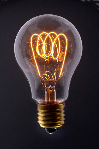
How Light Bulbs Work
Before the invention of the light bulb, illuminating the world after the sun went down was a messy, arduous, hazardous task. It took a bunch of candles or torches to fully light up a good-sized room, and oil lamps, while fairly effective, tended to leave a residue of soot on anything in their general vicinity.
When the science of electricity really got going in the mid-1800s, inventors everywhere were clamouring to devise a practical, affordable electrical home lighting device. Englishman Sir Joseph Swan and American Thomas Edison both got it right around the same time (in 1878 and 1879, respectively), and within 25 years, millions of people around the world had installed electrical lighting in their homes. The easy-to-use technology was such an improvement over the old ways that the world never looked back.
The amazing thing about this historical turn of events is that the light bulb itself could hardly be simpler. The modern light bulb, which hasn't changed drastically since Edison's model, is made up of only a handful of parts. In this article, we'll see how these parts come together to produce bright light for hours on end.

Light Basics
Light is a form of energy that can be released by an atom. It is made up of many small particle-like packets that have energy and momentum but no mass. These particles, called light photons, are the most basic units of light. (For more information, see How Light Works.)
Atoms release light photons when their electrons become excited. If you've read How Atoms Work, then you know that electrons are the negatively charged particles that move around an atom's nucleus (which has a net positive charge). An atom's electrons have different levels of energy, depending on several factors, including their speed and distance from the nucleus. Electrons of different energy levels occupy different orbitals. Generally speaking, electrons with greater energy move in orbitals farther away from the nucleus. When an atom gains or loses energy, the change is expressed by the movement of electrons. When something passes energy on to an atom, an electron may be temporarily boosted to a higher orbital (farther away from the nucleus). The electron only holds this position for a tiny fraction of a second; almost immediately, it is drawn back toward the nucleus, to its original orbital. As it returns to its original orbital, the electron releases the extra energy in the form of a photon, in some cases a light photon.
The wavelength of the emitted light (which determines its colour) depends on how much energy is released, which depends on the particular position of the electron. Consequently, different sorts of atoms will release different sorts of light photons. In other words, the colour of the light is determined by what kind of atom is exciting.
This is the basic mechanism at work in nearly all light sources. The main difference between these sources is the process of exciting the atoms.
How Lightning Works
Lightning is one of the most beautiful displays in nature. It is also one of the most deadly natural phenomena known to man. With bolt temperatures hotter than the surface of the sun and shockwaves beaming out in all directions, lightning is a lesson in physical science and humility.
Beyond its powerful beauty, lightning presents science with one of its greatest local mysteries: How does it work? It is common knowledge that lightning is generated in electrically charged storm systems, but the method of cloud charging still remains elusive. In this article, we will look at lightning from the inside out so that you can understand this phenomenon.
Lightning begins with a process that's less mysterious: the water cycle. To fully understand how the water cycle works, we must first understand the principles of evaporation and condensation.
Evaporation is the process by which a liquid absorbs heat and changes to a vapour. A good example is a puddle of water after rainfall. Why does the puddle dry up? The water in the puddle absorbs heat from the sun and the environment and escapes as a vapour. "Escape" is a good term to use when discussing evaporation. When the liquid is subjected to heat, its molecules move around faster. Some of the molecules may move quickly enough to break away from the surface of the liquid and carry heat away in the form of a vapour or gas. Once free from the constraints of the liquid, the vapour begins to rise into the atmosphere.
Condensation is the process by which vapour or gas loses heat and turns into a liquid. Whenever heat is transferred, it moves from a higher temperature to a lower temperature. A refrigerator uses this concept to cool your food and drinks. It provides a low-temperature environment that absorbs the heat from your beverages and foodstuffs and carries that heat away in what is known as the refrigeration cycle. In this respect, the atmosphere acts like a huge refrigerator to gas and vapours. As the vapours or gases rise, the temperatures in the surrounding airdrop lower and lower. Soon, the vapour, which has carried heat away from its "mother" liquid, begins to lose heat to the atmosphere. As it rises to higher altitudes and lower temperatures, eventually enough heat is lost to cause the vapour to condense and return to a liquid state.
Let's now apply these two concepts to the water cycle.

The Power Plant
Electrical power starts at the power plant. In almost all cases, the power plant consists of a spinning electrical generator. Something has to spin that generator -- it might be a water wheel in a hydroelectric dam, a large diesel engine or agas turbine. But in most cases, the thing spinning the generator is a steam turbine. The steam might be created by burning coal, oil or natural gas. Or the steam may come from a nuclear reactor like this one at the Shearon Harris nuclear power plant near Raleigh, North Carolina.
No matter what it is that spins the generator, commercial electrical generators of any size generate what is called3-phase AC power. To understand 3-phase AC power, it is helpful to understand single-phase power first.
The Power Plant: Alternating Current
Single-phase power is what you have in your house. You generally talk about household electrical service as single-phase, 120-volt AC service. If you use an oscilloscope and look at the power found at a normal wall-plate outlet in your house, what you will find is that the power at the wall plate looks like a sine wave, and that wave oscillates between -170 volts and 170 volts (the peaks are indeed at 170 volts; it is the effective (rms) voltage that is 120 volts). The rate of oscillation for the sine wave is 60 cycles per second. Oscillating power like this is generally referred to as AC, or alternating current. The alternative to AC is DC, or direct current. Batteries produce DC: A steady stream of electrons flows in one direction only, from the negative to the positive terminal of the battery.
AC has at least three advantages over DC in a power distribution grid:
- Large electrical generators happen to generate AC naturally, so conversion to DC would involve an extra step.
- Transformers must have alternating current to operate, and we will see that the power distribution grid depends on transformers.
- It is easy to convert AC to DC but expensive to convert DC to AC, so if you were going to pick one or the other AC would be the better choice.
The power plant, therefore, produces AC
The Power Plant: Three-phase Power
The power plant produces three different phases of AC power simultaneously, and the three phases are offset 120 degrees from each other. There are four wires coming out of every power plant: the three phases plus a neutral or ground common to all three. If you were to look at the three phases on a graph, they would look like this relative to ground:There is nothing magical about three-phase power. It is simply three single phases synchronized and offset by 120 degrees.
Why three phases? Why not one or two or four? In 1-phase and 2-phase power, there are 120 moments per second when a sine wave is crossing zero volts. In 3-phase power, at any given moment one of the three phases is nearing a peak. High-power 3-phase motors (used in industrial applications) and things like 3-phase welding equipment therefore have even power output. Four phases would not significantly improve things but would add a fourth wire, so 3-phase is the natural settling point.
And what about this "ground," as mentioned above? The power company essentially uses the earth as one of the wires in the power system. The earth is a pretty good conductor and it is huge, so it makes a good return path for electrons. (Car manufacturers do something similar; they use the metal body of the car as one of the wires in the car's electrical system and attach the negative pole of the battery to the car's body.) "Ground" in the power distribution grid is literally "the ground" that's all around you when you are walking outside. It is the dirt, rocks, groundwater, etc., of the earth.
Is it possible to generate electricity directly
from heat?
If you have a lot of heat, then you can do what power plants do -- you can use the heat to generate steam, and use the steam to spin a turbine. The turbine can drive a generator, which produces electricity. This setup is very common, but it requires a fair amount of equipment and space.
If you would like to generate electricity from heat in a simple way that has no moving parts, this usually involves thermocouples.
Thermocouples take advantage of an electrical effect that occurs at junctions between different metals. For example, take two iron wires and one copper wire. Twist one end of the copper wire and one end of one of the iron wires together. Do the same with the other end of the copper wire and the other iron wire. If you heat one of the twisted junctions (perhaps with a match) and attach the two free ends to a voltmeter, you will be able to measure a voltage. Similarly, if you hook the two iron wires to a battery, one junction will get hot and the other will get cold.
Interplanetary satellites that fly toward planets such as Jupiter and Saturn are so far away from the sun that they cannot use solar panels to generate electricity. These satellites use RTGs (radioisotope thermoelectric generators) to generate their power. An RTG uses radioactive material (like plutonium) to generate heat, and thermocouples convert the heat to electricity. RTGs have no moving parts, so they are reliable, and the radioactive material generates heat for many years.
What is the difference between two- and
three-pronged plugs?
Let's start with what the holes in an outlet do. When you look at a normal 120-volt outlet in the United States, there are two vertical slots and then a round hole centred below them. The left slot is slightly larger than the right. The left slot is called "neutral," the right slot is called "hot" and the hole below them is called "ground." The prongs on a plug fit into these slots in the outlet.
If you have read How Batteries Work, you know that electricity must flow in a circuit. In a battery, electricity flows from one terminal of the battery to the other. In a house outlet, power flows from hot to neutral. The appliance you plug into an outlet completes the circuit from the hot slot to the neutral slot, and electricity flows through the appliance to run a motor, heat some coils or whatever. Let's say you plug a light bulb into the outlet. The power will flow from the hot prong, through the filament and back to the neutral prong, creating light in the process.
What if you were to plug a thick strand of wire straight from the hot slot to the neutral slot of an outlet? Unlike an appliance, which limits the amount of electricity that can flow to 60 watts (for a light bulb) or 500 watts (for a toaster), the wire would let an incredible amount of electricity flow through it. Back in the fuse box, the fuse or circuit breaker for the outlet would detect this huge surge and it would cut off the flow of electricity. The fuse prevents the wires in the wall or the outlet itself from overheating and starting a fire.
The ground slot and the neutral slot of an outlet are identical. That is, if you go back to the fuse box, you will find that the neutral and ground wires from all of the outlets go to the same place. They all connect to ground (see How Power Distribution Grids Work for details on grounding). Since they both go to the same place, why do you need both?

If you look around your house, what you will find is that just about every appliance with a metal case has a three-prong outlet. This may also include some things, like your computer, that has a metal-encased power supply inside even if the device itself comes in a plastic case. The idea behind grounding is to protect the people who use metal-encased appliances from electric shock. The casing is connected directly to the ground prong.
Let's say that a wire comes loose inside an ungrounded metal case, and the loose wire touches the metal case. If the loose wire is hot, then the metal case is now hot, and anyone who touches it will get a potentially fatal shock. With the case grounded, the electricity from the hot wire flows straight to ground, and this trips the fuse in the fuse box. Now the appliance won't work, but it won't kill you either.
What happens if you cut off the ground prong or use a cheater plug so you can plug a three-prong appliance into a two-prong outlet? Nothing really -- the appliance will still operate. What you have done, however, is disable an important safety feature that protects you from electric shock if a wire comes loose.
No comments:
Post a Comment